Rotary Switch/ Cam Switch


>> Download PDF (21.4MB)
LW30 Rotary Switch

>> Download PDF (1.05MB)
Introduction:
LW30 series rotary switches applied to circuits of AC 50Hz with working voltave up to 440V and rated working current up to 100A.LW30 is suitable to control:air-conditioner,water pump and ventilating equipments,and AC motors with small power.
LW30 series rotary switches have six current ratings:20A,25A,32A,40A,63A,80A and 100A.
LW30 series has the finger protection terminals,which offers an extra advantage.
LW30 series switches has Larger insulation distance,quick disconnectinvg response.And is a good choice For DC circuits.LW 30 has additional contact which enable us to install the contact separetely.
LW30 series rotary switches switches comply with:GB/T 14048.3,and IEC 60947-3.
Specification
| Description | LW30-25(20) | LW30-32 | LW30-40 | LW30-63 | LW30-80 | LW30-100 | ||||||||
| Rated thermal current | Ith | A | 25(20) | 32 | 40 | 63 | 80 | 100 | ||||||
| Rated working voltage | Ue | V | 240 | 440 | 240 | 440 | 240 | 440 | 240 | 440 | 240 | 440 | 240 | 440 |
| Ie/Pe | Ie/Pe | |||||||||||||
| AC-21A | A/KW | 20/- | 20/- | 32/- | 32/- | 40/- | 40/- | 63/- | 63/- | 80/- | 80/- | 100/- | 100/- | |
| AC-22A | A/KW | 20/- | 20/- | 32/- | 32/- | 40/- | 40/- | 63/- | 63/- | 80/- | 80/- | 100/- | 100/- | |
| AC-23A | A/KW | 15/4 | 15/7.5 | 22/5.5 | 22/11 | 30/7.5 | 30/15 | 43/11 | 43/22 | 57/18.5 | 57/30 | 70/22 | 70/37 | |
| AC-3 | A/KW | 11.7/3 | 11.7/5.5 | 15/4 | 15/7.5 | 22/7.5 | 22/11 | 36/11 | 36/18.5 | 43/15 | 57/30 | 57/18.5 | 57/30 | |
Dimension and Installation
-
Panel installation
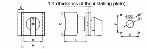
| Description | Dimensions(mm) |
Installation(mm) |
|||||||
| A | B | C | K | L | E | F | D1 | D2 | |
| LW30-20 | □64 | 42 | 54 | 13.5 | 61 | 48 | 48 | Φ10 | Φ4.2 |
| LW30-25 | □64 | 42 | 54 | 13.5 | 61 | 48 | 48 | Φ10 | Φ4.2 |
| LW30-32 | □64 | 42 | 54 | 13.5 | 61 | 48 | 48 | Φ10 | Φ4.2 |
| LW30-40 | □64 | 50 | 64 | 16 | 67 | 48 | 48 | Φ10 | Φ4.2 |
| LW30-63 | □64 | 50 | 64 | 16 | 67 | 48 | 48 | Φ10 | Φ4.2 |
| LW30-80 | □64 | 70 | 80 | 22.5 | 82 | 48 | 48 | Φ10 | Φ4.2 |
| LW30-100 | □64 | 70 | 80 | 22.5 | 82 | 48 | 48 | Φ10 | Φ4.2 |
-
Base installation
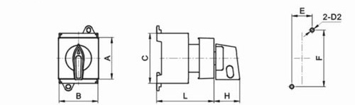
| Description | Dimensions(mm) | Installation(mm) | ||||||
| A | B | C | L | H | E | F | D2 | |
| LW30-20 | 45 | 42 | 54 | 50 | 26 | 22 | 60 | Φ4.2 |
| LW30-25 | 45 | 42 | 54 | 50 | 26 | 22 | 60 | Φ4.2 |
| LW30-32 | 45 | 42 | 54 | 50 | 26 | 22 | 60 | Φ4.2 |
-
Single hole installation
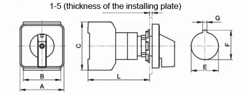
| Description | Dimensions(mm) | Installation(mm) | |||||
| A | B | C | L | E | F | G | |
| LW30-20 | □49 | 42 | 54 | 69 | 22.3 | 24.1 | Φ3.2 |
| LW30-20 | □64 | 42 | 54 | 69 | 22.3 | 24.1 | Φ3.2 |
| LW30-25 | □49 | 42 | 54 | 69 | 22.3 | 24.1 | Φ3.2 |
| LW30-25 | □64 | 42 | 54 | 69 | 22.3 | 24.1 | Φ3.2 |
| LW30-32 | □49 | 42 | 54 | 69 | 22.3 | 24.1 | Φ3.2 |
| LW30-32 | □64 | 42 | 54 | 69 | 22.3 | 24.1 | Φ3.2 |
-
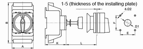
Installation of doorlock safety switch
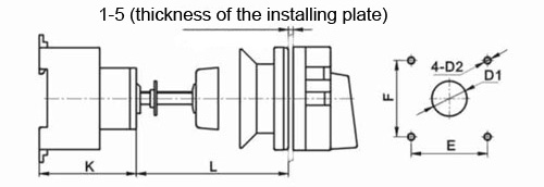
| Description | Dimensions(mm) | Installation(mm) | |||||
| K | L(min.) | L(max.) | E | F | D1 | D2 | |
| LW30-20 | 50 | 32 | 150 | 48 | 48 | Φ22 | Φ4.2 |
| LW30-25 | 50 | 32 | 150 | 48 | 48 | Φ22 | Φ4.2 |
| LW30-32 | 50 | 32 | 150 | 48 | 48 | Φ22 | Φ4.2 |
| LW30-40 | 61 | 32 | 150 | 48 | 48 | Φ22 | Φ4.2 |
| LW30-63 | 61 | 32 | 150 | 48 | 48 | Φ22 | Φ4.2 |
| LW30-80 | 68 | 32 | 150 | 48 | 48 | Φ22 | Φ4.2 |
| LW30-100 | 68 | 32 | 150 | 48 | 48 | Φ22 | Φ4.2 |
-
Protective cover
| Description | Dimensions(mm) | Installation(mm) | |||||||
| A | B | K | Lmin | Lmax | E | F | D1 | D2 | |
| LW30-80 | 70 | 133 | 68 | 32 | 150 | 48 | 48 | Φ22 | Φ4.2 |
| LW30-100 | 70 | 133 | 68 | 32 | 150 | 48 | 48 | Φ22 | Φ4.2 |
-
Plastic box
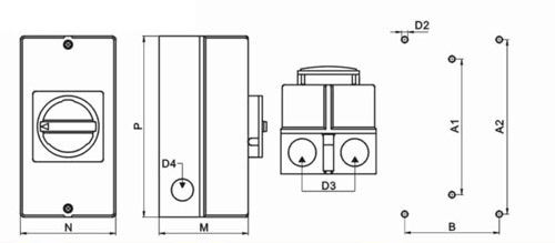
| Description | Dimensions(mm) | Installation(mm) | |||||||
| D3 | D4 | M | N | P | A1 | A2 | B | D2 | |
| LW30-20 | Φ23 | Φ19 | 85 | 83 | 160 | 150 | -- | -- | Φ4.2 |
| LW30-25 | Φ23 | Φ19 | 85 | 83 | 160 | 150 | -- | -- | Φ4.2 |
| LW30-32 | Φ23 | Φ19 | 85 | 83 | 160 | 150 | -- | -- | Φ4.2 |
| LW30-40 | Φ29 | Φ23 | 100 | 95 | 190 | 178 | -- | -- | Φ4.2 |
| LW30-63 | Φ29 | Φ23 | 100 | 95 | 190 | 178 | -- | -- | Φ4.2 |
| LW30-80 | Φ37.5 | Φ23 | 144 | 105 | 250 | -- | 229 | 124 | Φ6.5 |
| LW30-100 | Φ37.5 | Φ23 | 144 | 105 | 250 | -- | 229 | 124 | Φ6.5 |
